¶ Purpose
An electronic targeting folder can be used to detail specific targeting and weaponeering instructions to fighters in an operation. This page will detail how to construct these targeting folders and provide a template for mission makers to use.
¶ Folder Structure
¶ Cover Page
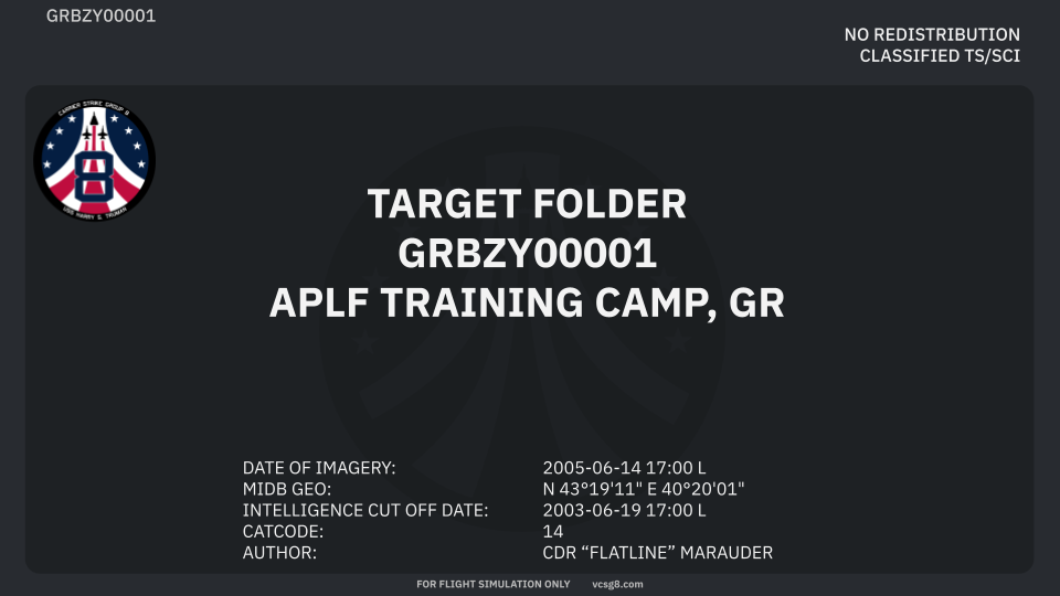
As the author of the targeting folder the following fields will be required to filled in:
The second line of the cover page will be a 10 character alphanumeric sequence with the following format: CCTTT#####. This is a unique identifier that will utilize a 2-character Country Code CC followed by a 3 character target location abbreviation TTT, and a 5-digit numeric designation #####. This 10-digit alphanumeric identifier is also known as the Basic Encyclopedia code or BE.
The third line of the cover page will have the target name in plain english followed by the country code.
The information block at the bottom of the cover page will have the following infromation:
| 1 | DATE OF IMAGERY | Date and time (local) that the imagery was collected on using the following format: 4-digit year (YYYY) - 2-digit Month (MM) - 2-digit day (DD) |
| 2 | MIDB GEO | Mission Database Geographic Reference - the Latitude and Longitudinal coordinates of the rough centeroid of the targeted facility or object given in degrees, minutes, and seconds DD°MM’SS" |
| 3 | INTELLIGENCE CUT OFF DATE | Date and time that imagery or intelligence packet will be considered out of date or expired. This cut off is up to the author’s discretion. Date and time will follow the same format as item 1. |
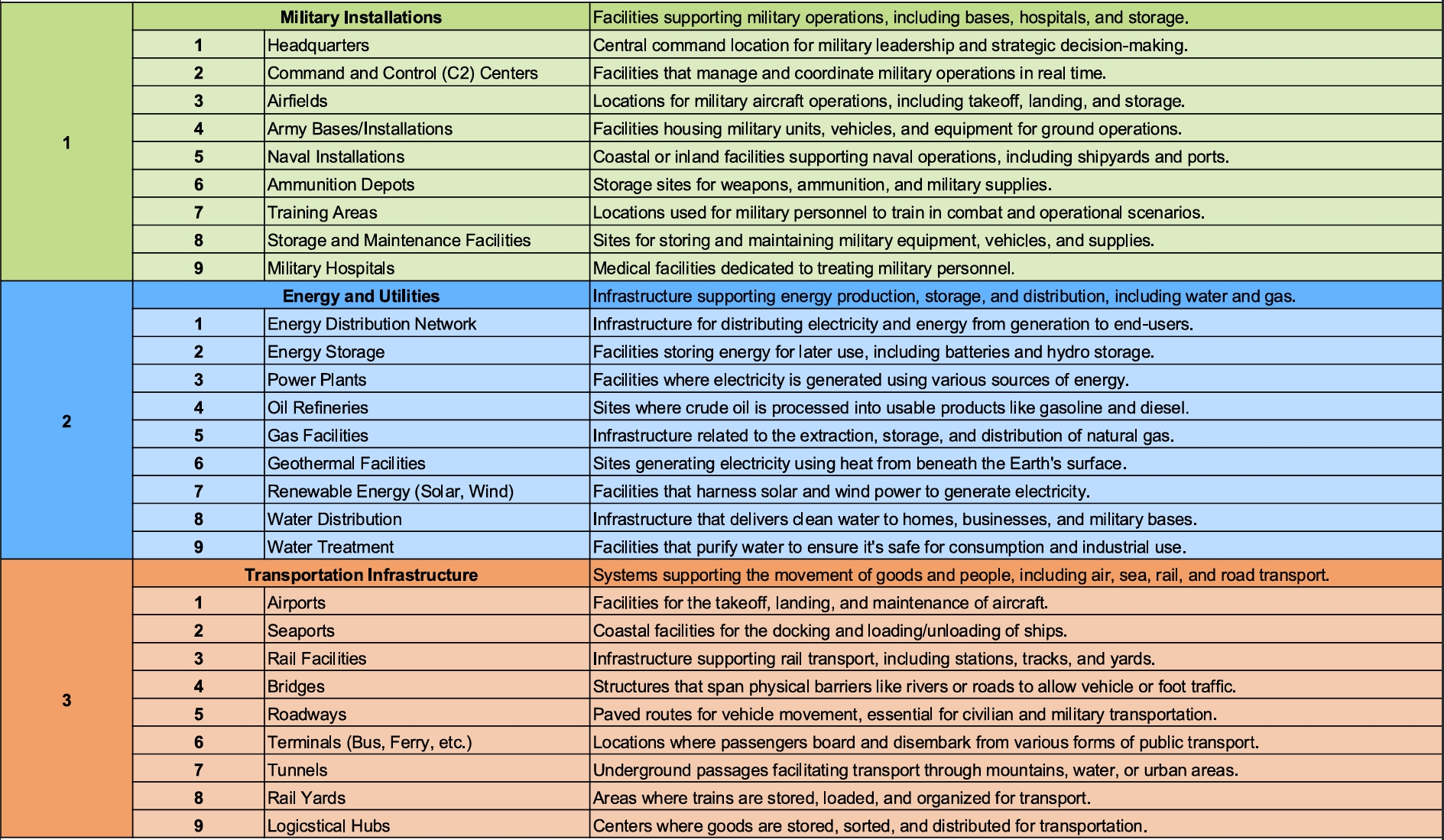
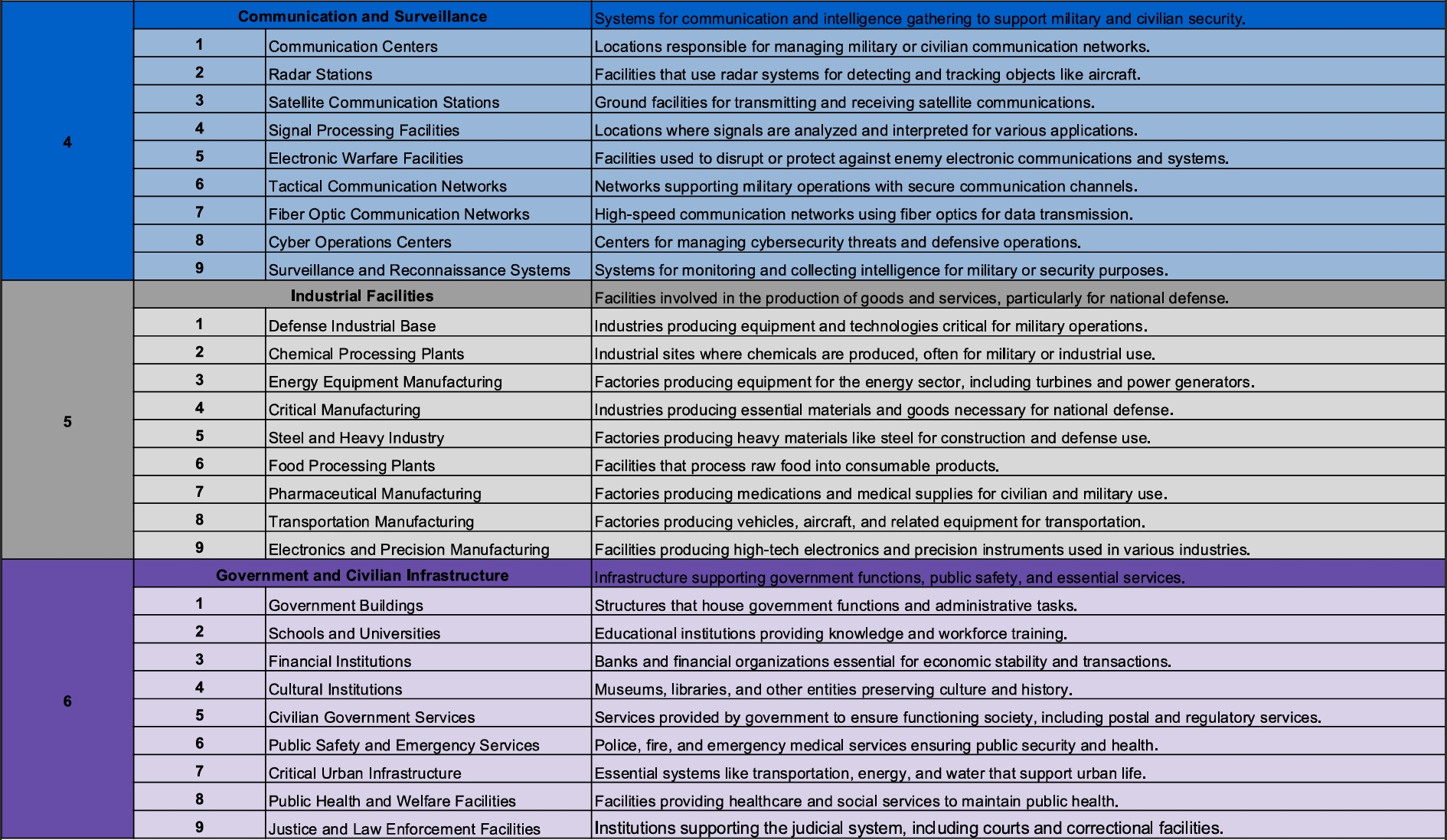
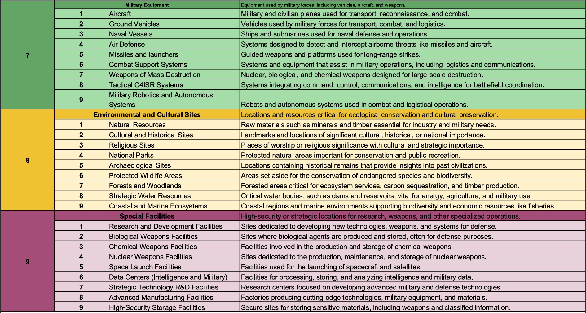
| 4 | CATCODE | Category Code - This will be a 2 digit code identifying the type of target. Reference pages 15-17 of the template slide deck provided. |
| 5 | AUTHOR | The authoring individual or organization |
¶ Joint Operations Graphic
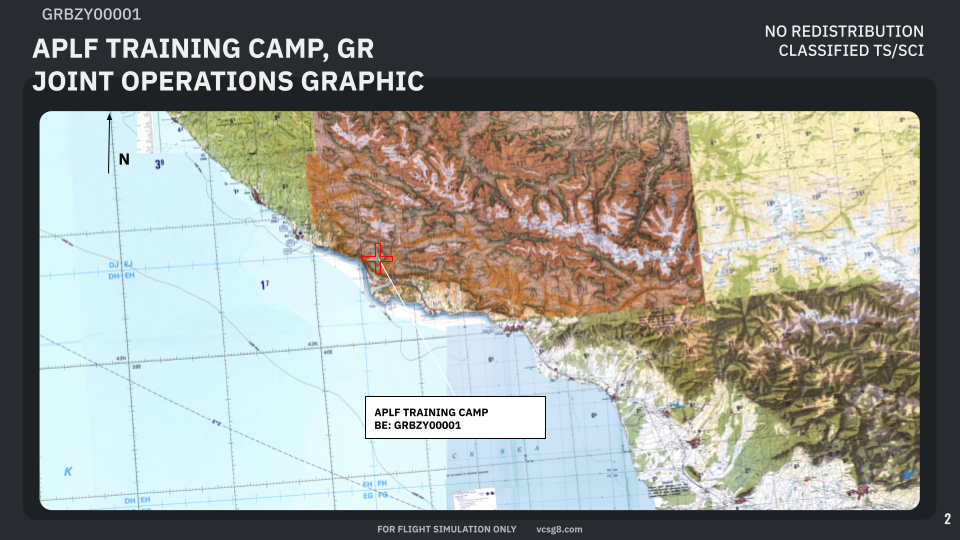
This page will utilize the MAP layer of DCS world and give the end user an overall orientation of the target in relation to the expected Area of Operations (AOR). This image should utilize a minimum of 10 NM scale zoom level when in the DCS mission editor.
A red cross will be used to indicate the target location and identify it with it’s target name and BE.
This graphic will always be north oriented.
¶ Orientation View Graphic
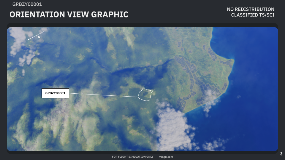
This graphic should be a satellite or similar image oriented in the expected ingress direction for the fighters utilizing the target folder.
This graphic will include a rough facility outline and the target’s BE as a label. If additional targets are in the field of view the author will include at the minumum BE labels for adjacent targets, and facility outlines if able.
A north orientation arrow MUST be included in this graphic.
¶ Facility Outline Graphic
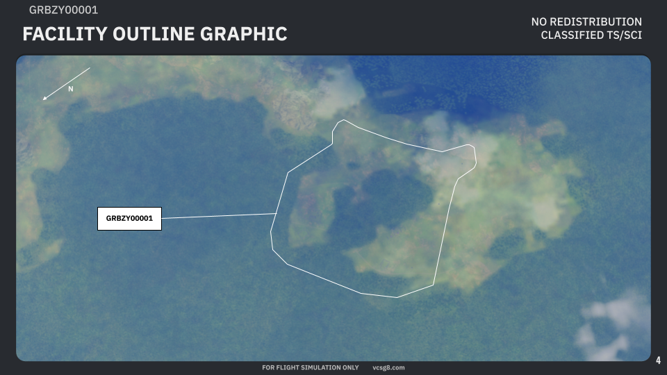
This graphic may be omitted if a more detailed facility outline will not provide additional information from the Orientation View Graphic (OVG).
If utilized, the Facility Outline Graphic will define the facility boundaries in greater detail at a greater magnification level while still providing an overall picture of the complete facility or installation being targeted.
An installation will be defined as a target containing multiple facilities within its boundaries. When defining an installation in a Facility Outline Graphic, a separate Installation Boundary will also be displayed in this graphic.
Each facility outline will be labeled with a unique BE.
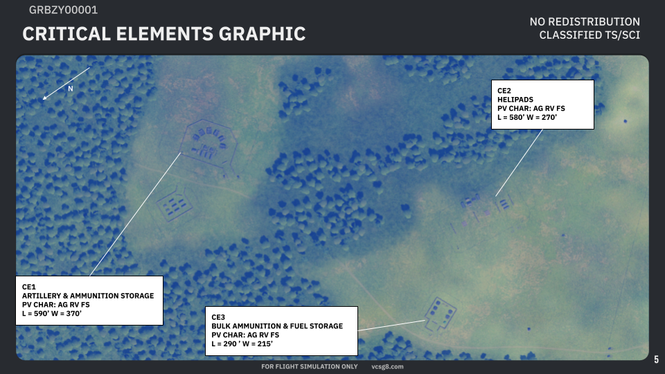
¶ Critical Elements Graphic
The Critical Elements Graphic will define in greater granularity the identified structures or elements critical to its function. Each of these will be labled as CE# or CE##
Each critical element will require the following infromation to be filled in by the author:
| 1 | NAME OR DESCRIPTION |
Short description of the object identified. |
| 2 | PV CHAR |
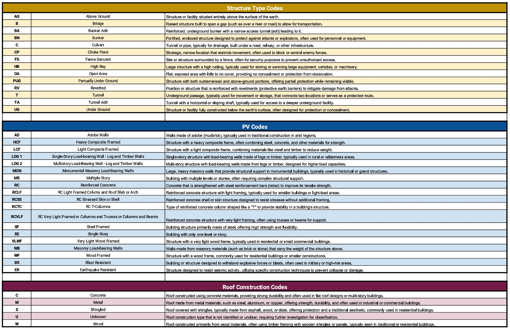
PHYSICAL VULNERABILITY CHARACTERISTICS - These will be listed as 2 character codes referencing the PV CHAR table in the targeting folder. |
| 3 | L x W |
The length and width of the structure, or structures, identified in the critical element, or the physical footprint of the identified element measured in feet. |
¶ Joint Desired Point of Impact Graphic
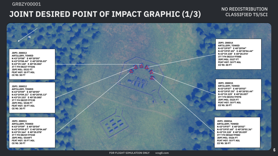
The Joint Desired Point of Impact or, JDPI, will identify the specific desired weapon impact points in 3-dimensional space. Each JDPI will be identified by a red triangle centered over the desired impact point and contain the following information:
| 1 | JDPI # | The JDPI number will be given as a 6-character alphanumeric designation with a leading character followed by a unique 5-digit number. |
| 2 | DESCRIPTION | Short description of the targeted object |
| 3 | DD°MM’SS" | The JDPI latitude and longitude coordinates in DD°MM’SS" format |
| 4 | DD°MM’SS.SS" | The JDPI latitude and longitude coordinates in DD°MM’SS.SS" format |
| 5 | DD°MM.MMM’ | The JDPI latitude and longitude coordinates in DD°MM.MMM’ format |
| 6 | MGRS | The JDPI coordinates in MGRS format with 10-digit accuracy (1 m ) |
| 7 | JDPI MSL | JDPI elevation in feet as measured from the mean sea level (MSL) |
| 8 | FEAT HT | Feature Height - height in feet of the feature being targeted |
| 9 | CE 90 | Circular Error 90% - the circular accuracy of the coordinates provided with 90% confidence. This item may be omitted if desired. |
¶ Weaponeering Options
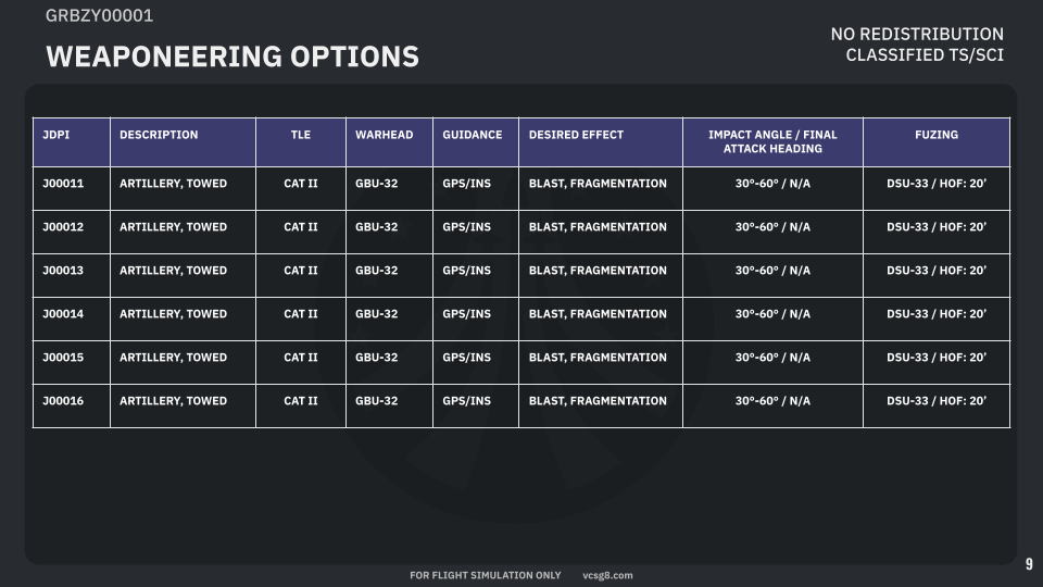
The weaponeering options table will list the author’s recommended, or sometimes directed, weapon-target pairing for each JDPI. This table will define the following parameters:
| JDPI | JDPI number/identifier |
| DESCRIPTION | JDPI description - may be identical to description in JDPI graphic(s) |
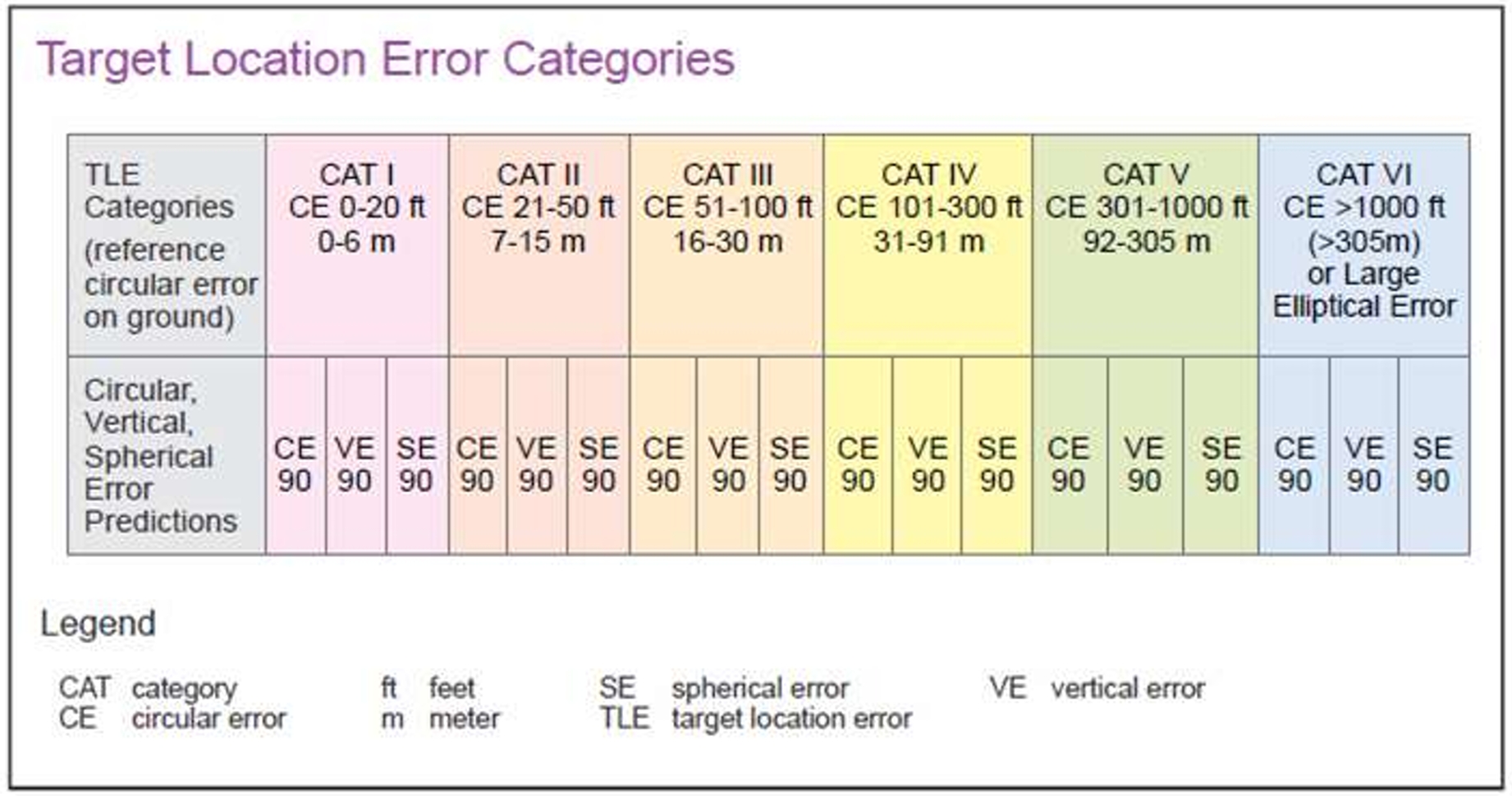
| TLE | Target Location Error Category - Accuracy of JDPI coordinates as described in the target location error reference attached to the target folder |
| WARHEAD | Type of warhead or specific munition to be used on the assigned JDPI |
| GUIDANCE | Weapon guidance package required for the assigned JDPI. Options are: GPS/INS, LASER, TV/EO, RADAR, or BALLISTIC for unguided munitions |
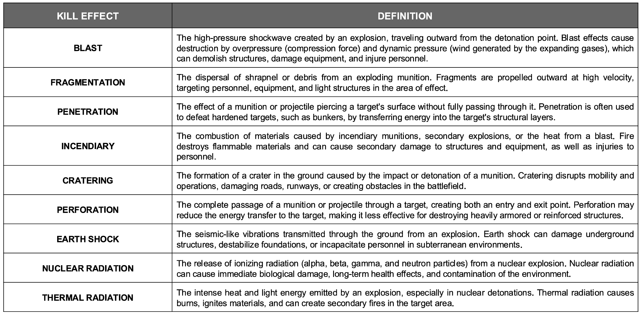
| DESIRED EFFECT(S) | The author or mission designer’s desired effects on the assigned JDPI. These effects can be found in the Military Kill Effects Reference page of the target folder |
| IMPACT ANGLE/FINAL ATTACK HEADING | The author or mission designer’s desired, or required, impact angle (as measured from the surface) and attacker’s final magnetic heading when releasing the muntion. This will be given as two sets of numbers divided by a / with the preceding number always being the impact angle, and the second number, or range, always being the final attack heading. |
| FUZING | The author or mission designer’s weapon fuze requirements to generate the desired military kill effects on the assigned JDPI. This will list the specific fuze option and settings found in the DCS armament windows. |
¶ Collateral Damage Estimation Graphic
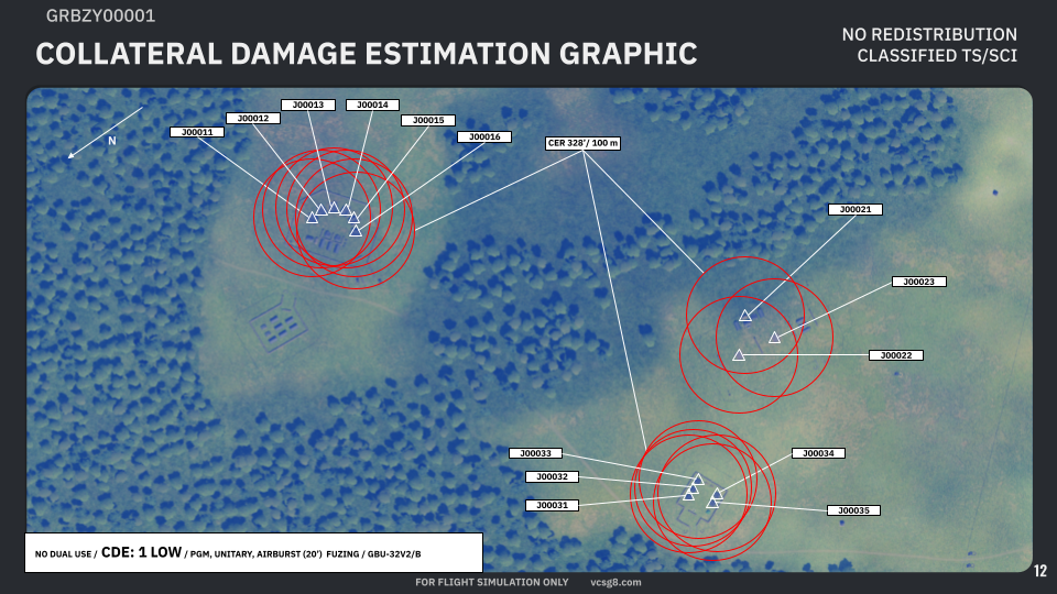
This graphic will show the collateral damages expected from the most destructive option in the weaponeering options list on all JDPIs.
JDPI’s will be identified by their JDPI numbers, and a white triangle only.
The Collateral Effects Radius, or CER will be visualized as a red circle or ellipse with its maximum extent/range being defined in both feet and meters.
A North orientation arrow must be present on this graphic.
The information card at the bottom of the graphic will list the following information:
| DUAL USE STATUS | Will define if the target facility is of civilian and military use (DUAL USE), military use only (NO DUAL USE), or if it is civillian use only (CIVIL ONLY). |
| CDE | Collateral Damage Estimation - the overall collateral risk assessment as defined in the Collateral Damage Estimation Methodology |
| WEAPON GUIDANCE | Options will be PGM for any precision guided munition, or BALLISTIC for any unguided munition |
| WARHEAD TYPE | Options will be UNITARY for high explosive payloads, and CLUSTER for weapon types employing submunitions |
| FUZING TYPE | Options will be CONTACT weapons functioning on contact with the target’s surface or the ground’s surface, AIRBURST for weapons that will function at a given height above the ground (given in feet), or DELAY for a weapon that will function with a delay after impact (given in milliseconds) |
| MUNITION | The weapon’s end-item designation |
¶ Collateral Damges Estimation Table
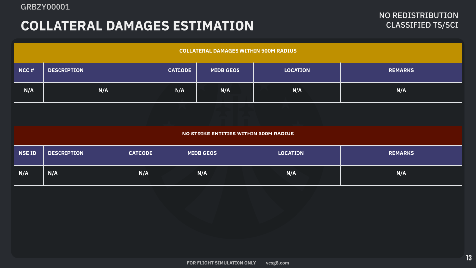
The Collateral Damages Estimation page will contain two tables: the first for the Nearest Collateral Concern(s) or NCC, and a second for any No Strike Entities, or NSE. These tables will contain the following information:
| NCC ID/# or NSE ID | A 2-5 digit numerical identifier for the assigned NCC or NSE |
| DESCRIPTION | A plain english description of the NCC or NSE |
| CATCODE | The 2-digit Category Code of the NCC or NSE |
| MIDB GEOS | Mission Database Geographic Reference - the latitude and longitudinal coordinates of the NCC or NSE |
| LOCATION | The location of the NCC or NSE relative to a given JDPI given as a magnetic or true bearing and range in feet from the defined JDPI |
| REMARKS | Any additional remarks given by the author or mission designer on the identified NCC or NSE |
¶ Reference Documents
¶ Military Kill Effects
¶ Physical Vulnerabilities
¶ Target Location Error
¶ Target Category Codes
¶ Categories

¶ Sub-Categories
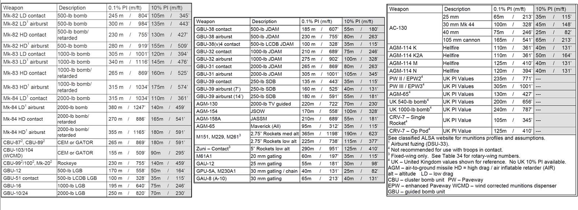
¶ Risk Estimate Distances by Weapon Type
¶ Collateral Risk Levels
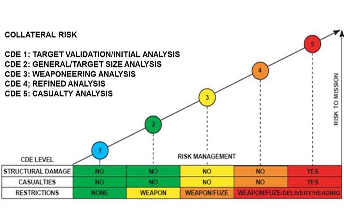
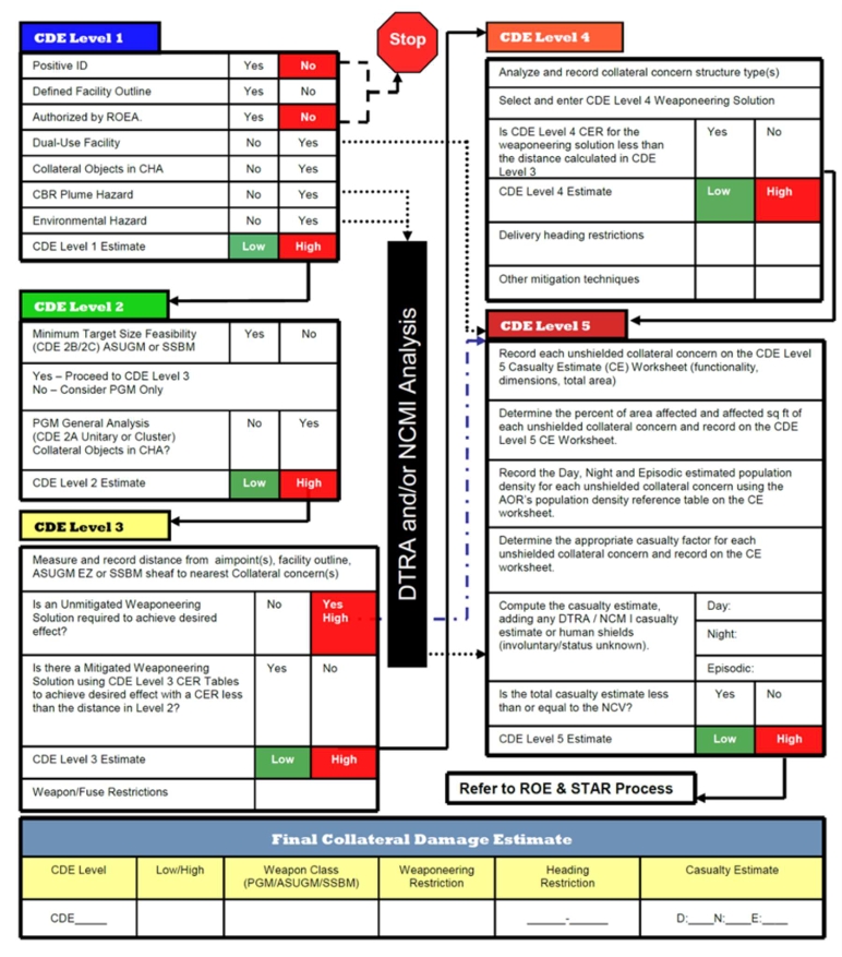
¶ Collateral Risk Estimation Methodology
¶ Template File
¶ Imagery Collection Techniques
Sourcing “satellite” imagery for DCS can take a multitude of forms, but the following will be discussed as best-use methods in order to provide players in vCSG-8 the most relevant data for our operations with the simulation environment.
¶ Mission Editor
Use of the SAT or satellite layer is the fastest way to provide overhead mapping of a target or object, but will not provide a “realistic” image feel. Use of this method should be reserved for instances where an author simply cannot produce better images given the amount of time available to produce a target folder.
It is recommended to remove visibility of unit icons when using this method if the author wishes to hide or obfuscate the exact target location.
¶ In-Game
Using the game simulation offers the best possible imagery as it will directly represent what a player will see while in their cockpit or sensors, however this method can be the most time consuming. The following factors must be considered when collecting images directly from the game engine:
| Time of Day | Satellite images provide the best contrast when collected approximately 1 hour after sunrise or 1 hour prior to sunset. |
| Weather Preset | Usage of the exact weather preset that players will experience during the mission/operation is not always recommended, as inclimate weather may mean cloud coverage over the target area or point of interest. If time permits use WeatherSpark to get the real-world weather data for the location you are collecting imagery for and set the DCS mission to the nearest matching weather preset for the time of day. |
Once the above have been set in the mission editor for the mission to be executed, run the simulation and use the free-look camera by pressing F10 to enter the map view, finding the object or area of interest on this map and zoom in on it. Once centered over your desired point of interest or object press L Ctrl + F11 to enter the free-look mode at the map location you are currently focused on.
Once in this free look mode, take position above your point of interest and move the camera as high as possible, this will usually result in the game registering the camera’s altitude at about 98,000 ft MSL. From this altitude utilize the field of view functions of the camera to narrow the field of view directly onto your point of interest using the R Ctrl and numberpad * keys to zoom in, and R Ctrl and numberpad / keys to zoom out. Zoom/field of view should be narrow enough to render 3D objects in the terrain or adjacent artificial structures.